
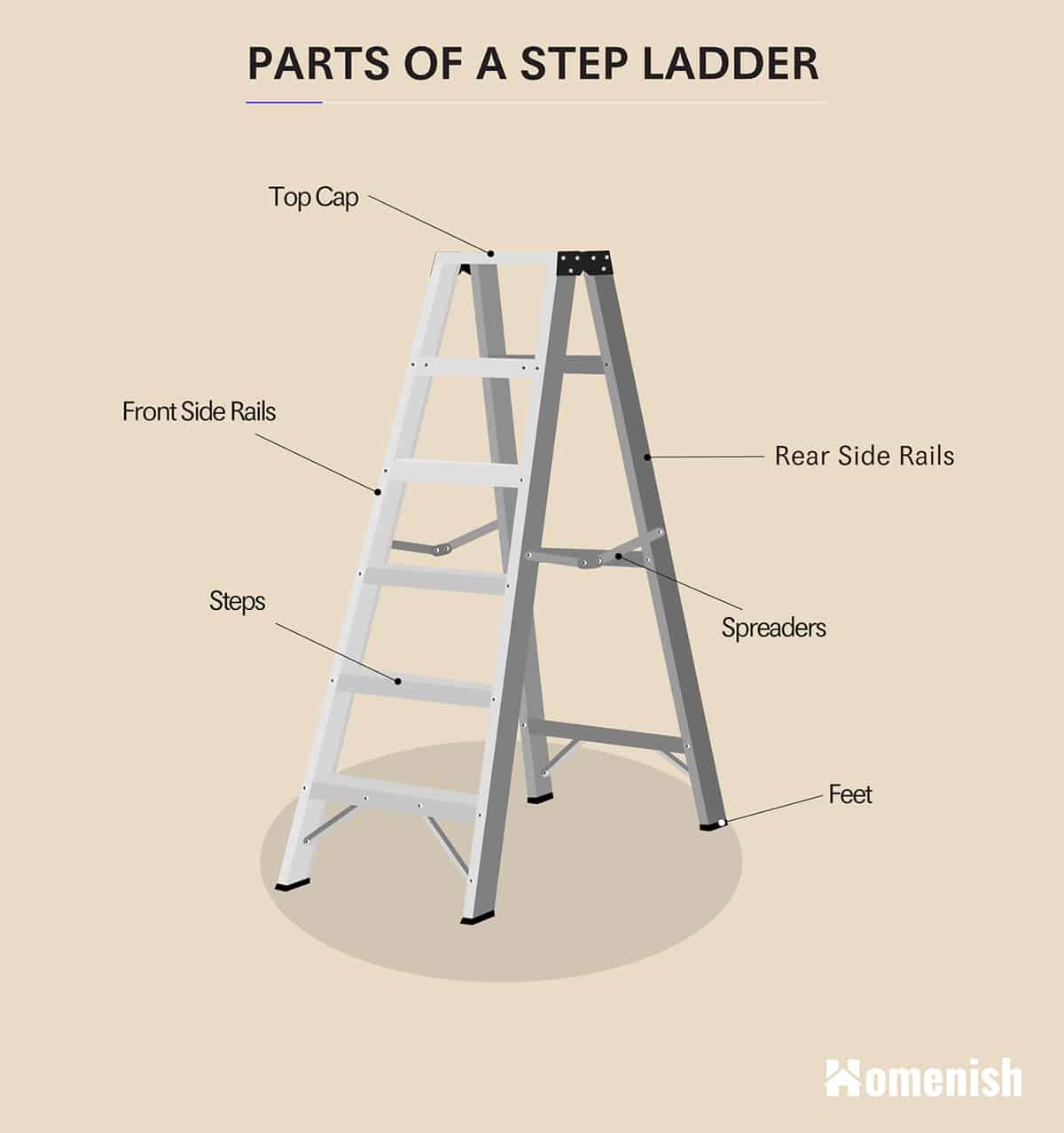
Parts of a Step Ladder Sunset Ladder & Scaffold Blog
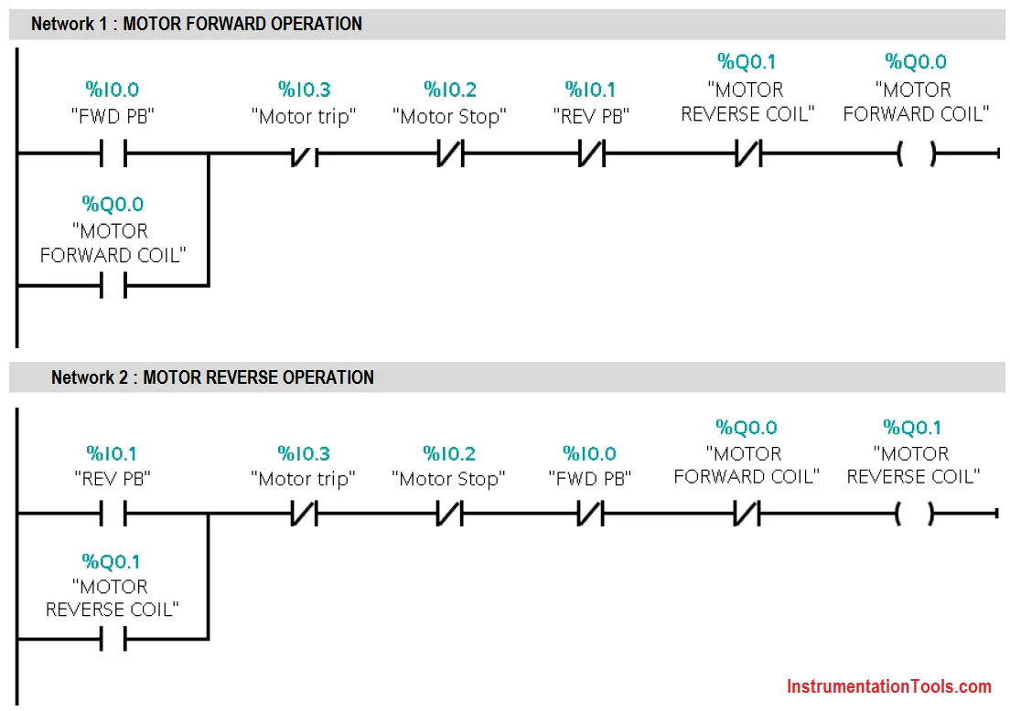
Ladder diagrams are to be thought of as virtual circuits, where virtual "power" flows through virtual "contacts" (when closed) to energize virtual "relay coils" to perform logical functions.
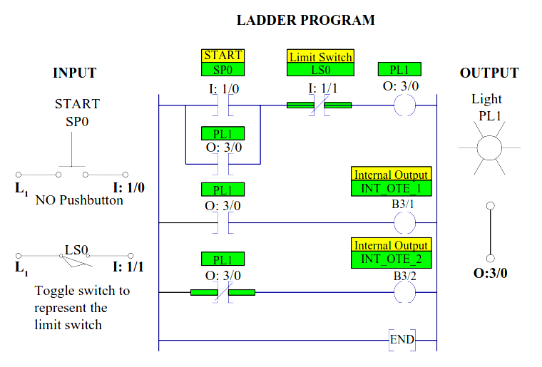
Ladder Diagram
What is Ladder Logic & Ladder Diagram? Ladder Logic is one of the top 5 most popular types of PLC programming languages used in manufacturing environments. Before Programmable Logic Controllers, manufacturing plants employed relay-based circuitry to energize different loads based on how the relays were wired together.
Ladder Diagrams Automation Community
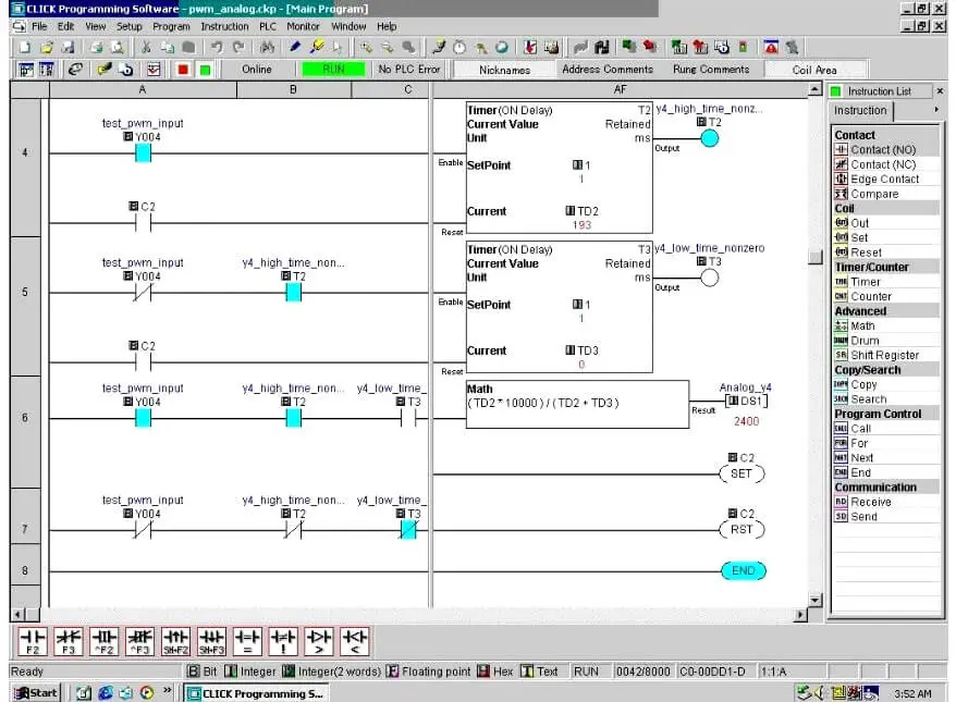
Ladder logic has evolved into a programming language that represents a program by a graphical diagram based on the circuit diagrams of relay logic hardware. Ladder logic is used to develop software for programmable logic controllers (PLCs) used in industrial control applications.

stairs parts diagram
A PLC Ladder Diagram is a graphical representation of the logical control functions performed by a Programmable Logic Controller. It is the language through which control and automation engineers communicate with PLCs to define their behavior and achieve desired outcomes in industrial processes.
Ladder Logic Basics Ladder Logic World
These diagrams documented how connections between devices were made on relay panels; they are called "ladder" diagrams because they are constructed in a way that resembles a ladder with two vertical rails and rungs between them.
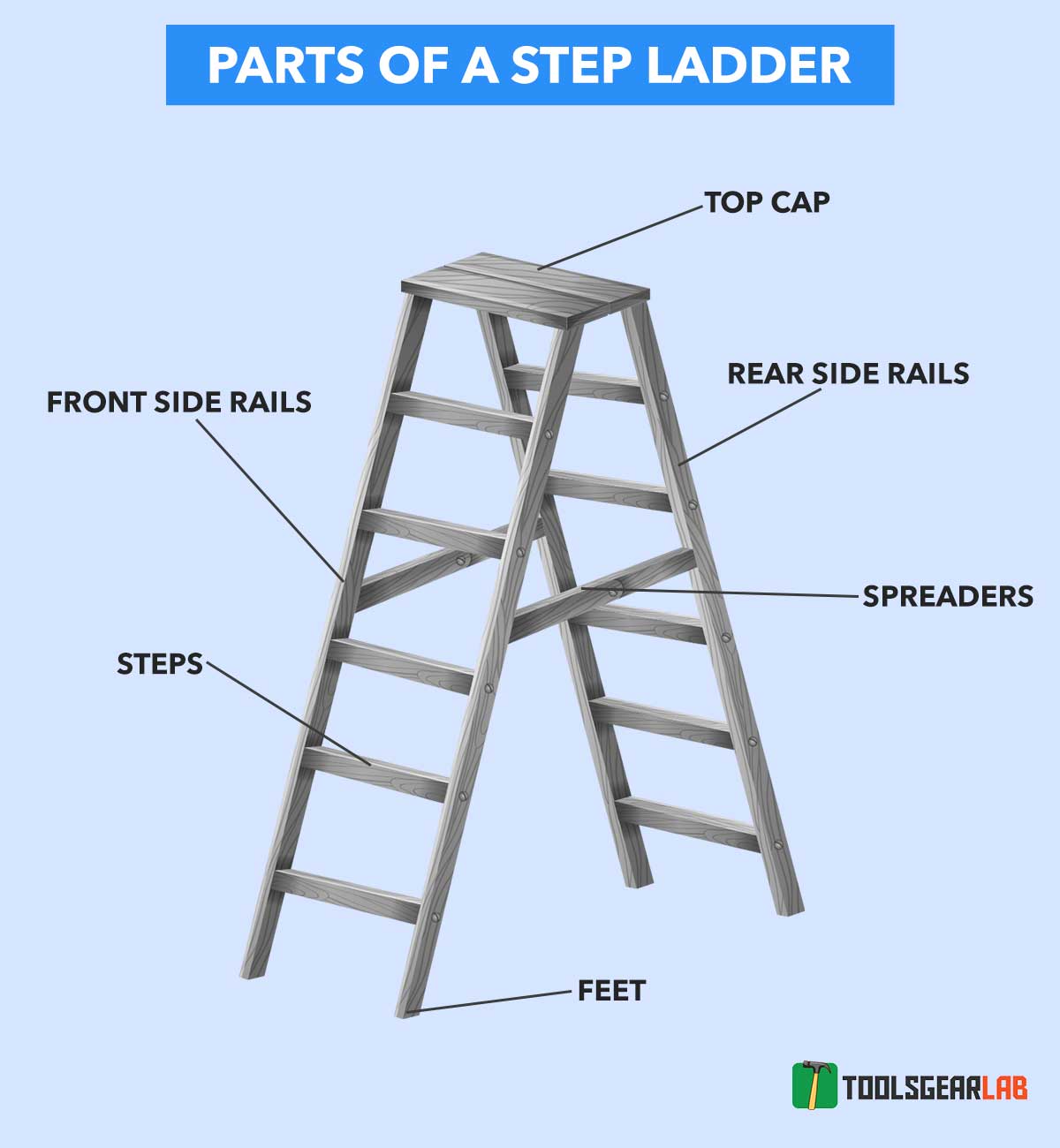
Parts Of A Ladder With Detailed Diagram Picture ToolsGearLab
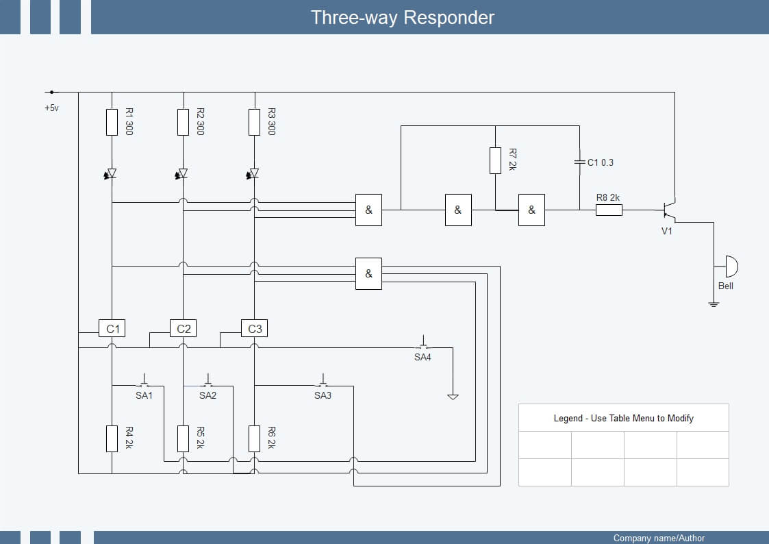
Ladder diagrams (sometimes called "ladder logic") are a type of electrical notation and symbology frequently used to illustrate how electromechanical switches and relays are interconnected. The two vertical lines are called "rails" and attach to opposite poles of a power supply, usually 120 volts AC.
Plc ladder diagram examples alienpase
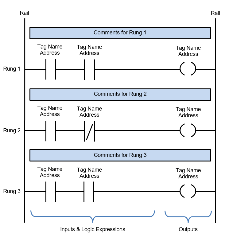
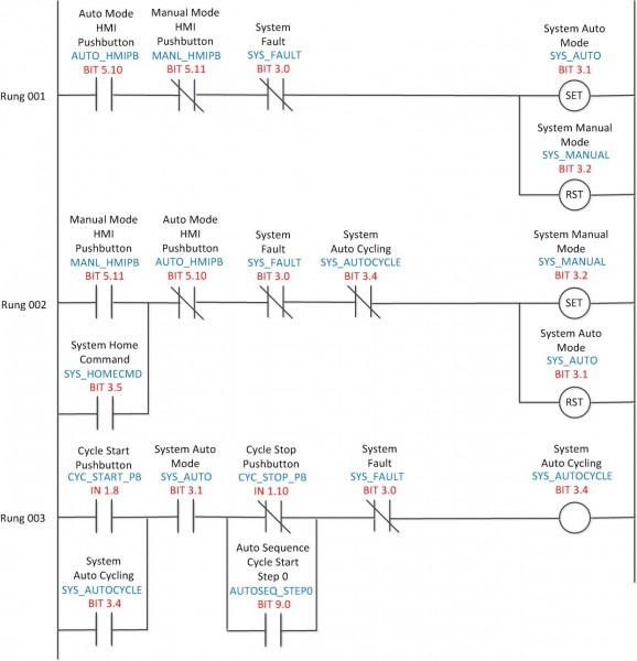
A ladder diagram is the symbolic representation of the control logic used for programming of a PLC. Ladder diagrams have horizontal lines of control logic called rungs and vertical lines at the start and end of each rung called rails. It looks just like a ladder, hence the name "ladder diagram".
Ladder Diagram Schematic Diagram Wiring Diagram Electrical Academia
Ladder diagrams (sometimes called "ladder logic") are a type of electrical notation and symbology frequently used to illustrate how electromechanical switches and relays are interconnected. The two vertical lines are called "rails" and attach to opposite poles of a power supply, usually 120 volts AC. L 1 designates the "hot" AC wire.
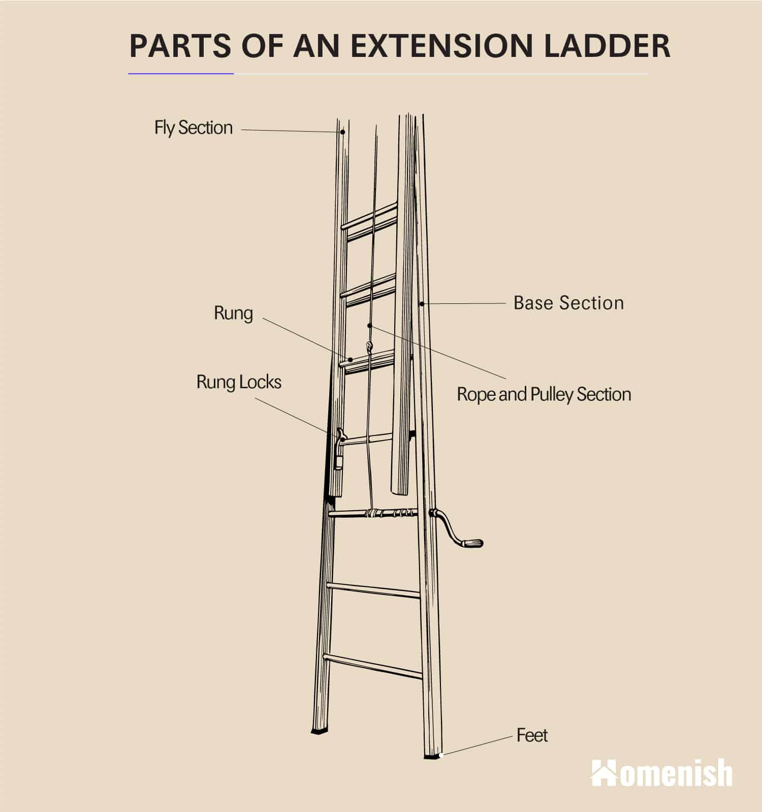
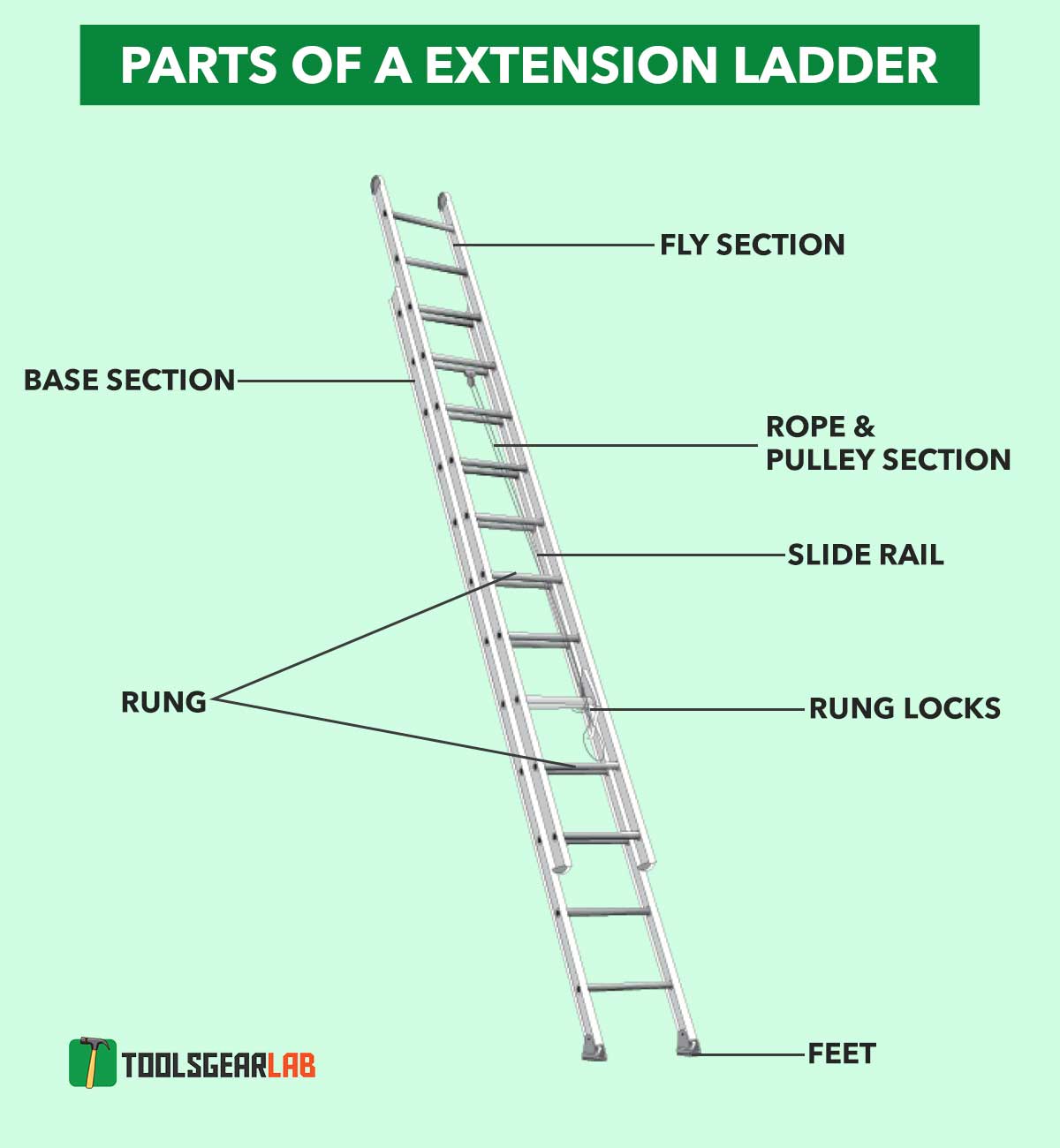
Parts of a Ladder (2 Diagrams For Step Ladder & Extension Ladder
Ladder diagrams are to be thought of as virtual circuits, where virtual "power" flows through virtual "contacts" (when closed) to energize virtual "relay coils" to perform logical functions. None of the contacts or coils seen in a Ladder Diagram PLC program are real; rather, they act on bits in the PLC's memory, the logical.
Parts of a Ladder (2 Diagrams For Step Ladder & Extension Ladder
Ladder logic diagram are graphical programming language which executes through real time input. It has two vertical line, which is called as rails, the left rail supplies power to the circuit, then it passes through each rung. Each rung has switches and output coil.
Ladder Diagram EdrawMax
Ladder diagrams symbols are the basic building blocks of a Ladder Circuit Diagram and these symbols are used in the PLC Programming. Here are some Symbols which are given below with their names and we also provide a symbol table, there you can find all ladder symbols with their names and their description. 3. Tips for Using Ladder Diagram Symbols
What is Ladder Diagram Programming ? Basics of PLC PLC Tutorials
Ladder diagrams are specialized schematics commonly used to document industrial control logic systems. They are called "ladder" diagrams because they resemble a ladder, with two vertical rails (supply power) and as many "rungs" (horizontal lines) as there are control circuits to represent.
Ladder Diagram Examples
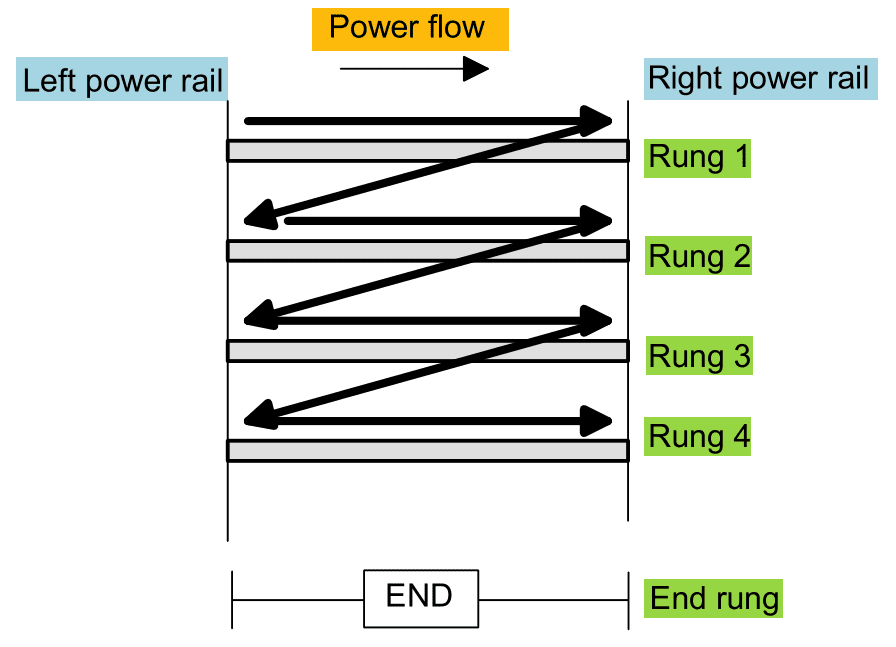
Follow the Flow: A ladder diagram showcases power flowing through paths, usually from left to right, across lines known as "rungs." Understand the path, and you've got the basic structure down. Grasp the Logic: Beyond just symbols, you need to decipher the logic. This logic flow traces the power path, helping you fathom how one action.

[DIAGRAM] Drawing Ladder Diagram
Ladder diagrams are advanced schematics widely used to record logic structures for industrial controls. These are called ladder diagrams because they mimic a ladder, with two vertical rails (supply power) and as many "rungs" (horizontal lines) as there are to represent control circuits.
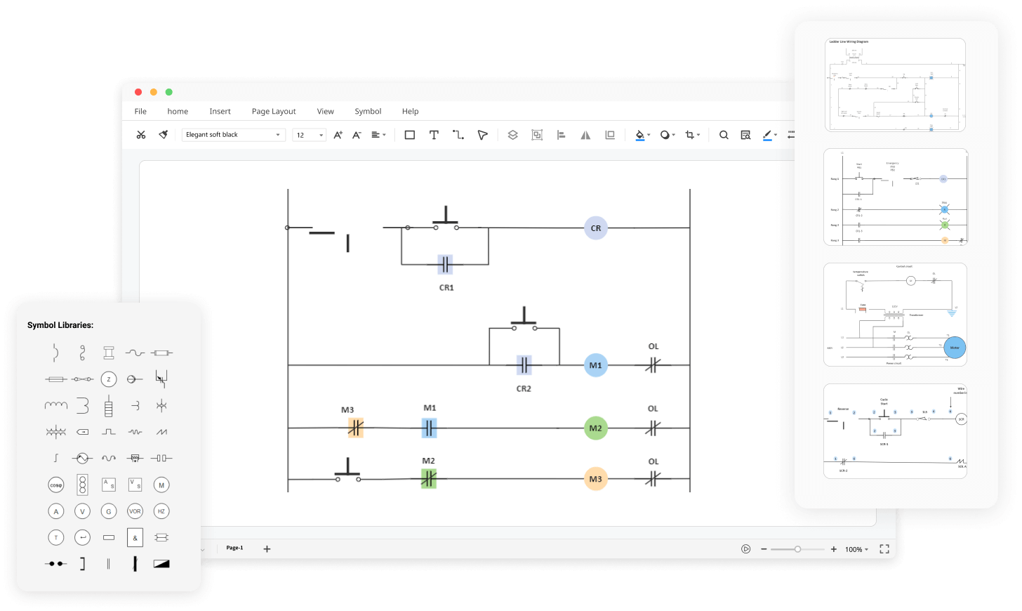
Free Online Ladder Diagram Maker EdrawMax Online
A graphical representation of the programming elements. The name " ladder diagram " is derived from the program's resemblance to a ladder with two vertical rails and a series of horizontal rungs between them. The rails are called "power rails" in the ladder diagram. Fig. 9.3 illustrates a typical ladder diagram and its conventions.
What is Ladder Diagram and How to Draw a Ladder Diagram?
Ladder diagrams are complex schematics widely used to record logic structures for industrial controls. EdrawMax Online helps understand how to create a ladder diagram online using free ladder diagram software. MAKE LADDER DIAGRAM NOW How to Make a ladder diagram Online Step 1: Start with login Step 2: Open blank canvas or select a template
