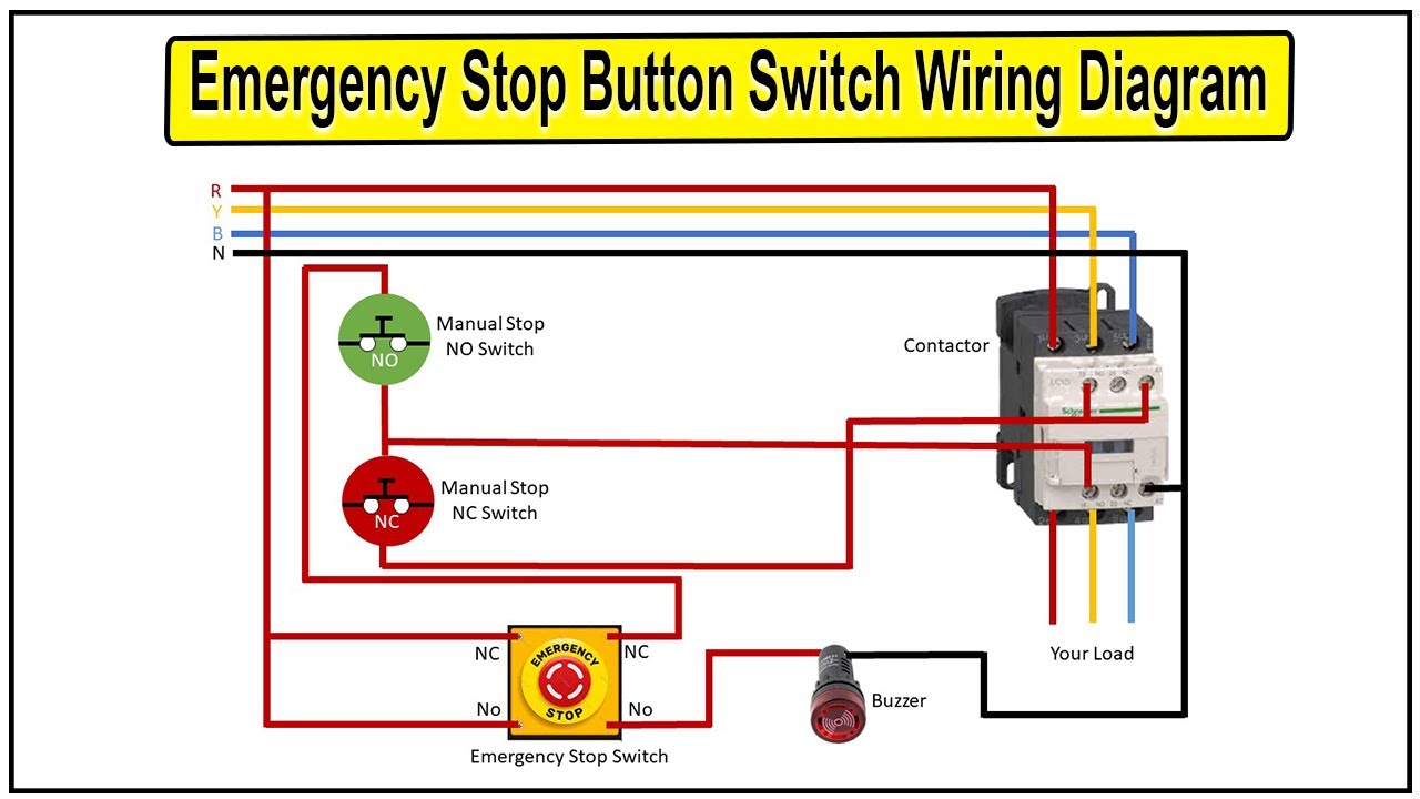
How to Wire an Emergency Stop Button Diagram (Walkthrough and Steps)
Using an emergency stop button bypasses that need by automatically activating the stop push button switch and disconnecting the load from the main power supply. Don't get overwhelmed by the wire connections and components present in the diagram.

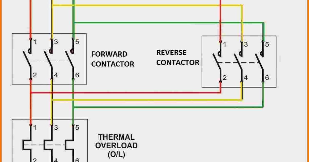
Emergency Stop Switch Connection with DOL Starter YouTube
For simple drives, the supply-disconnecting device (main switch) can be used as an emergency stop switch under certain circumstances. However, switching off the energy supply must not cause hazardous situations (stop category 0 in accordance with EN ISO 13850).
Emergency Stops and Guard Circuits AutomationPrimer
Emergency stops and pilot devices. An emergency stop device is used to permit anyone to stop machinery if it breaks down or if someone is in danger. We offer different types of traditional mushroom head type emergency stop for different types of mounting and environment. We also offer pull wire emergency stop switches which allow emergency.
E Stop Wiring Diagram
Simply put, an emergency stop function is a function that is initiated by a human action and is intended to shut down equipment in the case of an emergency. Device Defi nition The emergency stop device is a manual control device. It is the method of initiating the emergency stop function.
How To Make Emergency Stop Button Switch Wiring Diagram Emergency
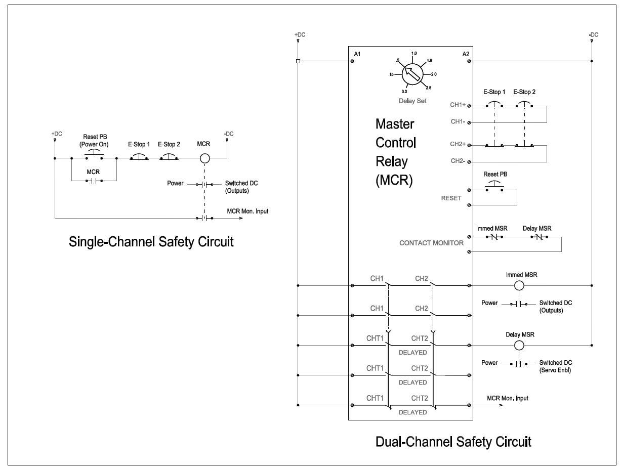
The Estop Safety Function has a functional safety rating of PLd Category 3 for both the CB3 and the e-Series. See the User Manual for the details including the PFHd values. The Safeguard Stop Safety Function is PLd for all UR cobots, however CB3 is Category 2 while the e-Series is Category 3. Inputs are to be the same state, with low being the.
How to Wire an Emergency Stop Button Diagram (Walkthrough and Steps)
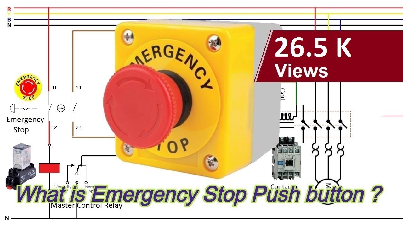
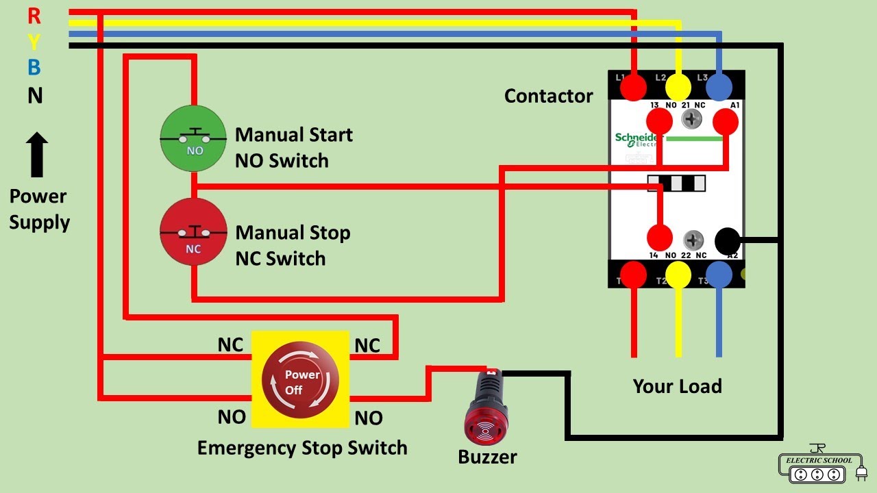
When the emergency stop button is pressed, the safety relay detects the button signal and opens its contacts causing the main contactor to open. Opening of the contactor disables the power input to the drive causing the motor to coast to a standstill.

Emergency Stop Switch Wiring Diagram
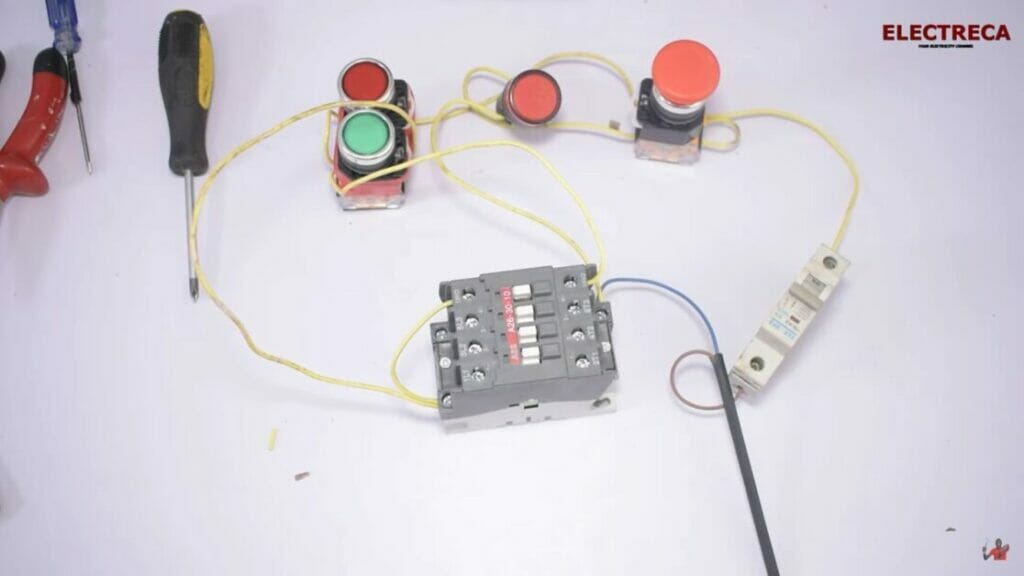
Wiring an emergency stop button isn't as easy as installing a lightswitch. In this video I show how to correctly wire a NC-NO (normally closed/normally open).
E Stop Wiring
What is the difference between a safety relay and general purpose relay? Why can't we just connect the estop to a PLC? How do you wire a basic emergency stop.

Emergency Stop Wiring Diagram Uk
LineStrong is a pull wire emergency stop switch, used for easy reach of the emergency stop function along machines and sections of conveyors. A pull wire emergency stop switch allows to initiate the emergency stop command from any point along the installed wire length by pulling the wire. It replaces a series of emer-
Schematic Emergency Stop Button Wiring Diagram Worksly
**for correct wiring please see wiring diagram below. video is incorrect****this video only applys to machines running grbl****users with a duet controller p.
Schematic Emergency Stop Push Button Wiring Diagram
The standards that dictate how an e-stop switch works are ISO 13850:2015, Safety of Machinery - Emergency Stop Function—Principles for Design; and IEC 60947-5-5, Low-Voltage Switchgear and Controlgear—Part 5.5: Control Circuit Devices and Switching Elements—Electrical Emergency Stop Device with Mechanical Latching Function.

Emergency Stop Wiring Diagram
In this video the practical wiring of the emergency stop button wiring.This video explains how to incorporate an emergency stop button in the control circuit.

e stop wiring diagram ZefhremAmani
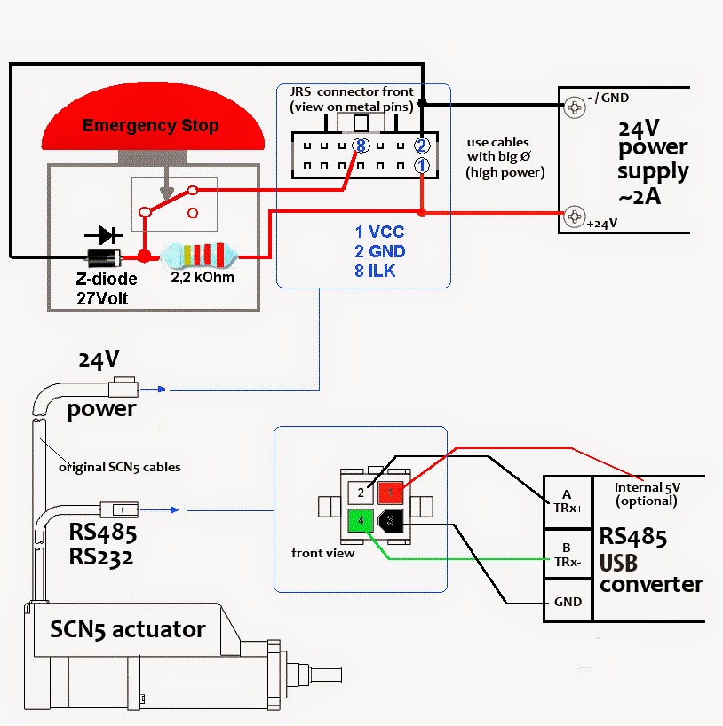
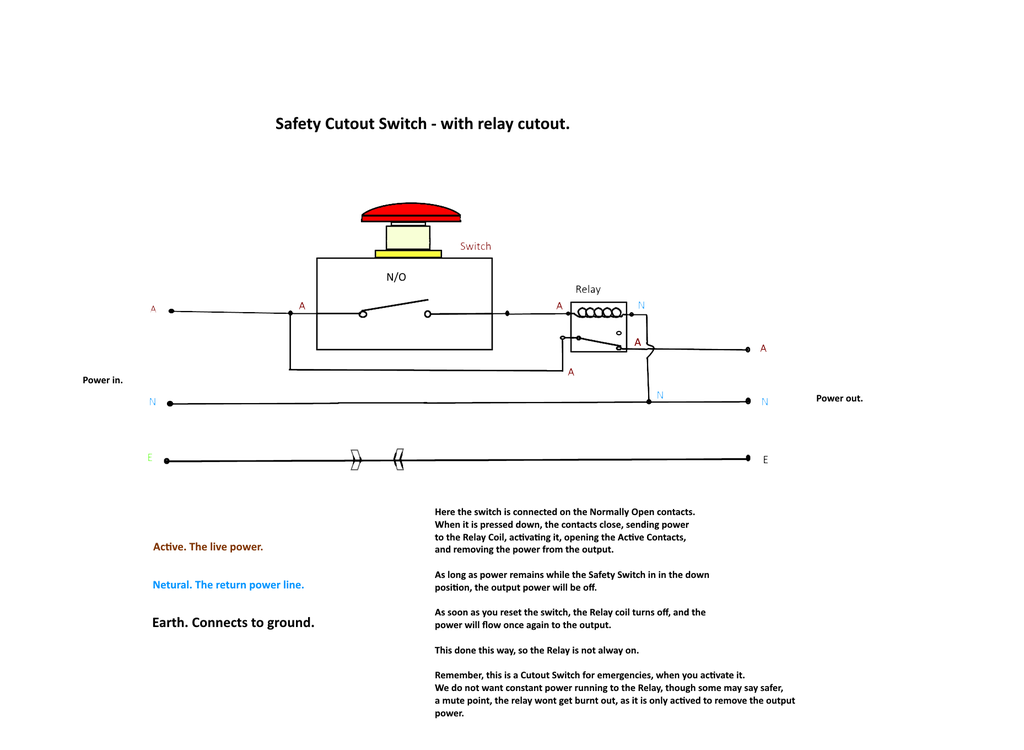
The safe way of wiring an emergency stop is in a normally closed manner. That means that the switch is normally closed, and the two terminals are connected. By connecting one end to logical 1, and pulling the other end to logical 0 through a resistor, it can be used to determine the state of the emergency stop.

Emergency Stop Wiring Diagram
Faults at the E-stop button, wiring terminals, or 440C-CR30 relay are detected before the next safety demand. This emergency stop function is complementary to any other safeguards on the machine and does not reduce the performance of other safety-related functions. The safety function in this example is capable of connecting and interrupting
wiring diagram for emergency stop
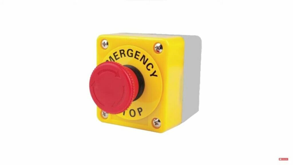
Emergency stop buttons, also known as E-Stops or kill switches, are used to reduce the risk of injury by stopping machinery quickly. Emergency stop buttons are fitted for easy access in any emergency. E-Stops are red and must feature a yellow background, bezel, or housing for attention.

Emergency Stop Schematic Circuit Diagram
In this episode we will learn how emergency push buttons are wired the correct way. and why not the other way.Consider support via donation from the link u.
